PROJECT / Reverse Engineering Glass Grinding for Robotic Automation
Reverse Engineering Glass Grinding for Robotic Automation
Reconstructing a conventional glass-lens grinding process from video and rebuilding it as a robotic workflow, with a custom compensated end effector.
Some manufacturing processes are difficult to automate — especially those developed around machines, habits, and experience that were never designed to be transferred directly into a robotic cell. This project started with exactly that kind of problem: an established glass grinding process that worked on a conventional machine, but was not suitable for flexible robotic automation in its original form.
The application focused on grinding and polishing large, curved glass parts such as optical lenses and design glass components. These parts are challenging because the tool has to follow a complex surface while maintaining stable contact with the workpiece. In glass finishing, the result depends not only on the tool path, but also on contact pressure, tool orientation, abrasive suspension, feed speed, tool material, and process stability. Small changes in any of these parameters can affect the quality of the surface.
The real challenge was how to translate an older, mechanically driven grinding process into a modern robotic workflow while preserving the important technological conditions that made the original process work. A conventional machine can create the required motion through a combination of rotating workpiece movement and mechanical tool movement. A robot, however, has to reproduce that process in a completely different way: through programmed motion, controlled tool orientation, and a suitable end effector.
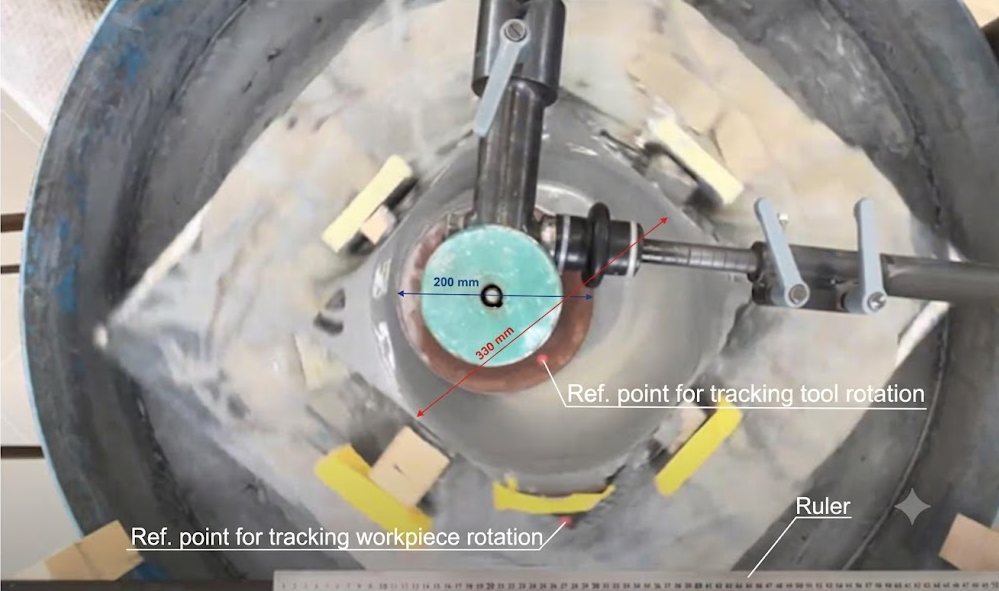
I began by analysing the original process used for grinding spherical glass lenses. The existing technology used a LOH HLP-500 machine, where the workpiece rotated on a table and the tool followed an additional mechanical motion. The grinding tool was a cast-iron disc, and the abrasive medium was a suspension of cerium oxide and demineralized water. The tool was not actively driven in the same way a conventional spindle would be; its rotation was strongly influenced by contact and friction in the process.
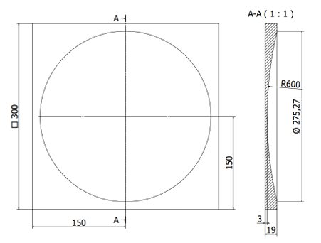 Drawing of the polished part
Reverse engineering the tool path
One of my favourite parts of the project was reconstructing the tool path from the original grinding machine. Since the goal was to transfer an existing proven process into a robotic environment, I did not want to invent the trajectory from nothing. The original machine already produced a functional motion pattern, so I treated it as valuable process knowledge that could be captured, analysed, and transformed into robot data.
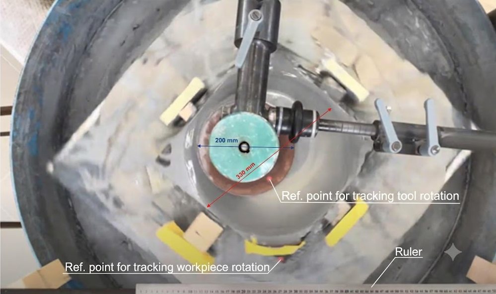
To do this, I recorded the grinding process from above. The original process involved two motions happening at the same time: the workpiece rotated on the machine table, while the tool followed its own mechanical movement. For a robot, this combined motion had to be converted into a trajectory relative to a stationary workpiece.
I used Blender as a practical reverse-engineering tool for this step. Although Blender is mainly known for 3D modelling, animation, and CGI, it also has strong video editing and motion tracking capabilities. I imported the recorded video into Blender and used it to analyse the movement of the tool frame by frame.
The first challenge was removing the rotation of the workpiece. In the robotic workplace, the glass part would not rotate, so the tool path had to be reconstructed as if the workpiece were stationary. I digitally compensated for the rotation by rotating the video in the opposite direction around the centre of the workpiece. Because the exact rotation speed was not known, I defined this correction manually using keyframes. I placed keyframes at selected moments in the video so that a reference point on the workpiece stayed aligned throughout the recording.
After this correction, the workpiece appeared stationary in the video, and the remaining visible motion represented the tool trajectory relative to the glass surface. This was the key step: it separated the useful tool path from the motion of the original machine.
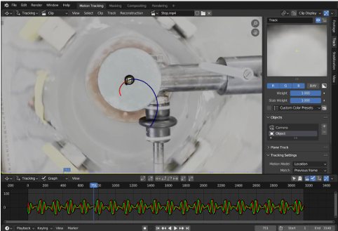
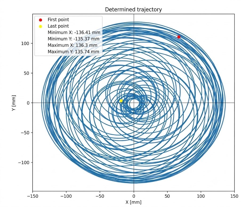
Next, I used Blender's motion tracking tools to follow the tool movement. Since there was no dedicated marker placed on the tool shaft during recording, I used the visible tool shaft itself as the tracking reference. In most frames, Blender was able to track the motion automatically. In sections where the contrast was not strong enough and the tracking became unreliable, I corrected the tracked position manually. This gave me a sequence of tool positions across the video.
The tracked data was still not directly usable for robot programming. Blender gave me coordinates in pixels, and the origin of the image coordinate system was located in the corner of the video frame. For robot programming, I needed coordinates in millimetres and a more useful coordinate system placed relative to the glass part.
To solve this, I used a ruler visible in the recorded setup as a scale reference. By comparing the known real-world length with the number of pixels in the video, I converted the tracked path from pixels into millimetres. I also shifted the coordinate system so that the origin corresponded to the centre of the workpiece. This turned the video analysis into usable manufacturing data.
At this stage, I had reconstructed the original machine's tool path as a digital 2D trajectory. It was not yet a complete robotic path, because it still had to be projected onto the curved glass surface and supplemented with correct surface normals. But this step created the foundation for the whole robotic workflow. It transformed an older mechanical process into data that could be used for offline robot programming.
Robot selection
To create a robotic alternative, I first had to define the process parameters that should be preserved. From the existing process, I identified the key values: tool rotation, an average feed speed, and a target contact force. These values became the starting point for the robotic system. Instead of blindly designing a new machine, I treated the original technology as a reference process and used it to define the requirements for the reverse-engineered solution.
The selected robotic workplace was based on a KUKA KR 90 R2700 pro industrial robot. This robot offered a large working range and sufficient payload, which is important for large-format glass applications. This is also one of the reasons why robots are attractive for this type of task. Compared with CNC machines, industrial robots are generally less rigid and less accurate under load, but they offer much better reach, flexibility, and access to complex geometries. For finishing operations such as grinding and polishing, where cutting forces are lower than in heavy machining, that trade-off makes sense.
Designing the compensated end effector
A major part of the project was the design of a custom machining spindle with axial compensation of the tool position. This was necessary because a robot alone cannot reliably solve every contact problem during grinding. Industrial robots have limited stiffness, and even small deviations in the surface, fixture, or trajectory can change the real contact force between the tool and the workpiece. For a glass finishing process, this is a serious issue. If the tool pressure is too low, the process becomes ineffective. If it is too high, the surface quality can suffer, the tool can wear faster, or the part can be damaged.
For that reason, I designed the end effector around the idea of local compensation. Instead of relying only on the robot joints to react to deviations, the compensation mechanism is placed directly at the tool. This allows the system to react more naturally to small axial position errors and helps maintain more consistent tool pressure against the glass surface.
I compared three possible compensation principles: gravitational, pneumatic, and electric. A gravity-based system is simple and similar to the original machine, but it is not flexible enough for different tool orientations — it only works properly when the tool is oriented vertically, because the useful force changes as the spindle tilts. An electric compensation system offers good control, but it increases cost and complexity, especially if a linear servomotor is used. The final concept used pneumatic axial compensation, because it offered the best balance of flexibility, control, construction complexity, and cost.
The selected pneumatic compensator provided active position measurement, force regulation, and a sufficient movement range for the application. This choice was important because the end effector had to do more than hold a rotating tool. It had to become a compliant technological interface between the robot and the glass surface.
Solving the spindle and mechanical layout
Another challenge was the spindle drive itself. Standard machining spindles are usually designed for much higher speeds, often thousands of revolutions per minute. The required speed for this process was very low, around 36 rpm, so a typical high-speed spindle was not suitable. Instead, I selected a compact servo drive with a cycloidal gearbox, the TG Drives DS 70, which could operate in the required low-speed range while providing sufficient torque.
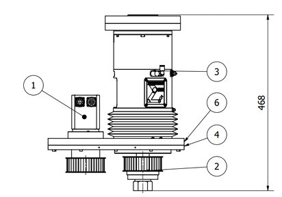
The spindle layout also required careful mechanical design. A simple inline arrangement of the compensator, motor, spindle, and tool would have made the end effector too long. That would increase the risk of vibration, reduce accessibility, and make the robot less convenient to use around a large workpiece. To avoid this, I placed the servo drive outside the main compensation axis and transferred rotation to the tool through a timing belt drive.
This solution kept the tool in the axis of the compensation unit, which reduced unwanted tilting moments, while allowing the motor to sit beside the spindle rather than behind it. I designed the belt drive with a 1:1 ratio, because the required output speed was already achieved by the selected servo drive. The system used a toothed belt to ensure stable motion without slip.
The mechanical construction was designed as a modular assembly. I divided the end effector into separate functional modules: the drive module, the driven spindle and chuck module, and the robot-compensator mounting module. This modular approach made the design easier to assemble, service, and modify. It also made the system more practical as an experimental platform, where individual parts may need to be changed during testing.
I also completed the necessary engineering checks for the design. This included calculating the required torque to overcome friction between the tool and glass surface, checking the pin connections for shear and contact pressure, and verifying the bearing arrangement. The design used angular contact ball bearings in an X arrangement to support the driven pulley and tool mount. Even though the selected bearings were oversized for the low operating speed, they were suitable for the required shaft diameter and loading conditions.
 Modular construction of the end effector
Offline programming and practical verification
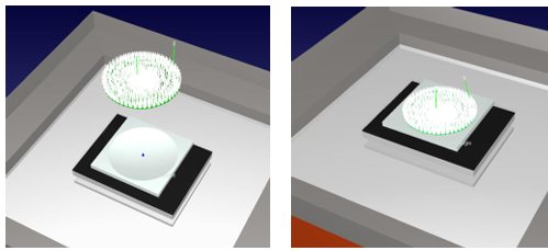
The next step was offline robot programming in RoboDK. I built a virtual version of the robotic workplace, including the KUKA robot, the custom end effector, the tool, the table, and the glass workpiece. This made it possible to prepare and check the process before running it on the real robot. For machining and finishing operations, offline programming is especially useful because the robot must follow a continuous trajectory with the correct tool orientation, not just move between a few discrete points.
The trajectory reconstructed from the original machine was first available only as a 2D path. For the real process, it had to be projected onto the curved surface of the glass lens and supplemented with correct surface normals. The tool must stay perpendicular to the surface during grinding, otherwise the contact conditions change. I used RoboDK together with its Python API to project and redefine the trajectory so that the robot could follow the spherical surface correctly.
The final result was a complete robotic grinding concept: a custom compensated spindle, a defined technological process, a reconstructed and adapted tool path, a virtual robot cell, and a robot program generated through offline programming. The simulation was transferred to the real robotic workplace, and the robot trajectory matched the prepared simulation.
Next steps and takeaways
The next logical step would be to continue development with bonded abrasive tools instead of loose abrasive suspension. The tested process used a free abrasive medium, which works well for a concave lens because the suspension naturally stays in the lowest part of the surface. For more complex design surfaces or surfaces tilted away from gravity, keeping the abrasive suspension in the cutting zone becomes much harder. Bonded tools would make the process more suitable for a wider range of robotic glass finishing applications.
This project was valuable to me because it combined several engineering areas that I enjoy: robotics, mechanical design, reverse engineering, manufacturing technology, CAD modelling, process analysis, and offline programming. It was not only about designing a part or programming a robot. It was about understanding an existing production method deeply enough to rebuild it in a modern form.